

Team
Members
Brian
Klug
Mike Tran
Nabeel
Kibria
Garret Skinner
Justin
Bell
John Sargent
[email protected]
(Sends E-mail to
all members)
ii.
Table of Contents
i. Title
Page
ii. Table
of Contents
1. Abstract
2.1
Description
2.2
Specifications
2.3
Constraints
3.1
Configuration
3.2
Analysis of Parts
3.3
Materials
3.4
Program
3.5
Program Output
4. Drawings
4.1
Concept Drawing
4.2
Assembly
4.2.1
Sub Assembly
4.3
Detail Drawings
4.4
Electrical Schematic
5.1
Parts List
5.2
Cost Estimate
5.3
Special Thanks
5.4
Conclusion
1.
Abstract
Our
goal as a team is to assemble a highly accurate electronic scale with an
efficient digital display of weight and postage.
We have been given approximately three months to reach this ultimate
goal. The three months will serve
as time in which we will consult within our group to construct initial design
proposals, final design proposals, initial and final design specifications and
drawings. Finally, we will assemble, test and present our final product to the
class. Our ultimate goal can only
be achieved if all these sequential goals are achieved one by one.
Throughout
the first month and a half the team consulted each other and multiple
references in order to propose different designs that met and exceeded the
specifications for our electronic scale.
After searching various Internet sites and magazines the team finally
decided on what we wanted our scale design to be.
We settled on a simple yet effective design.
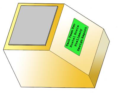
The scale design we chose is that of a simple lightweight box with a
slanted face and backlit LCD screen.
The
design also calls for the back panel to open on a hinged side, which will
allow us to access the inner constituents.
The opening will also serve as a window for those who wish to examine
the inner components of the scale in an educational setting.
Once
our design proposition was finalized, the team began to master ProEngineer, a
computerized 3-D drawing and assembly board.
Within two weeks the final designs, 3-D drawings, and 3-D assembly
designs had been completed. Once
these steps were completed the team began analyzing the mathematics behind
building the actual processor and electronics of the scale.
The team also began to analyze how the strain gauge and wheatstone bridge
setup could most effectively be utilized for integration with the A/D converter.
This is the point at which the team is positioned and working on to this
date.
The
team will take recess for one week for spring break and then resume work on the
scale. The individual parts will be acquired, or manufactured.
The team will mount the strain gauge on the bar, and build the electronic
system. The processor will be
programmed at this point, and we will begin modifications.
2.
Design
2.1 Description
The scale will be an enclosed
device, with an aluminum pan to hold the weight of the sample.
A thin aluminum bar, 1/4"
inch in width and 1/8"
in height, will support this pan by a vertical rod.
Attached to this beam will be a 120W
strain gauge. This strain gauge
will be mounted directly under the pan’s support piece for maximum efficiency.
The gauge will be connected within a wheatstone bridge, which will
deliver its output to an amplifier. The voltage of the amplifiers output (0 to
+5V) would be directed into a 12Bit A/D converter.
This data will be sent via digital I/O lines to Parallax’s Stamp II
microprocessor. This information
will then be will be converted to a weight in grams, and a formula will then
calculate the correct postage and display this on the backlit LCD screen. This screen will be mounted angled towards the user for
maximum readability. This robust
design should have no problems due to its simplicity, yet the power of the
embedded system will provide the user with a state-of-the-art full-featured
scale. The scale will automatically zero itself during initial power-up, and
enter low-power consumption sleep mode. The
scale leaves sleep mode when an object is placed on the pan and the backlight on
the LCD turns on while the display shows the correct output.
The scale turns “off” after approximately 35 seconds of inactivity.
2.2 Specifications
q
Max weight: 2000g
q
Accuracy: +/- 0.5g (0.025% of max weight)
q
Temperature range: 0º to +50º C
q
Operating Relative humidity: 90% max non-condensing
q
Power: Unregulated 9 Volts DC dry-cell
q
Power Consumption: 108mA
q
Power Capacity: 2000mAh
q
LCD Color: Yellow green (Easy to read, large display)
q
“Hi Tech” scale appeals to young students.
q
Back panel hinged for students to learn from inside component
arrangement.
2.3 Constraints
q
Accuracy will always be +/- 0.5g, including objects
with low weight.
q
The LCD’s backlight consumes 90mA, accounting for most of the
power consumed by the unit.
q
The fluid in the LCD display is the limiting component for the
operative temperature range and operating relative humidity.
q
The maximum weight was given to the design team.
3.
Analysis
3.1 Configuration
The electronic microprocessor-controlled scale was chosen because of its high
level of accuracy, professional user interface, ease of use, and powerful
features offered. Strain gages are
excellent tools to determine accuracy in pressure. One advantage of choosing an
electronic strain gauge is that it is accurate and fast in determining the
weight of an object. Compared to other scales such as mechanical or hydraulics
scale, electronic scales are smaller and more compact. To measure the weight of bigger objects also, using a strain
gage is more accurate compared to mechanical scales in determining the weight of
the object. While mechanical and
hydraulics scales are often cheaper, electronic scales seem to be more appealing
because the processor does the calculation in determining the weight of an
object. Although the cost of electronic components are higher than mechanical
components, using today's technology such as in strain gages and processors has
its advantages such as in determining the precise weighing of an object.
The
basic designs of our electronic scale is similar to the design of a typical
digital scale, however with added power of our feature-packed processor. The
reason why we choose this design is that it is simple to read the scale compared
to the spring scale or mechanical scale. The capability we have with a
processor controlled scale is almost limitless. In our electronic scale, the
weight is and postage is simply displayed on the LCD screen. The object to be
weighed is put on top of our electronic scale. The mechanism that zeros our
electronic scale is through the processor. It is a software routine that sets
the digital value to zero when there is no pressure on the strain gage. The
software approach in a scale is important, as it allows us greatest flexibility.
We can program postal rates easily, and add features without changing
hardware.
3.2 Analysis of parts
Ø
The pan will hold the items to be weighed.
We have chosen a pan that will provide the user with a reasonably large
weight surface, for ease of use.
3.3 Materials
The pan we use is made of wood and metal. We
basically decided to make our scale from wood because it was cost effective and
easily build where metal structure of an electronic scale are harder to build.
Even though the look of our scale is not as swift and elegant as if it would if
made from metal. It brings an old American Style of look along with the advance
technical use of its features. The slant use of the LCD display is a nicer to be
read. Our source of energy comes from 5 volts of power to our electronic scale
and we used battery as our energy source because it is the best method with the
compliment of the strain gage.
3.4 Program
Below
is a QBASIC Program and its output. This
program was used to generate and test values to give us the correct values.
We feel this program has enabled us to perform a large number of
experimental values, which allowed us to quickly create accurate figures.
CLS
‘Input data
r0 = 120 ‘ Resistance of strain guage
r2 = 120 ‘R2 in bridge
r3 = 120 ‘ R3
r4 = 120 ‘ R4
b = .25 ‘ base
h = .125 ‘ height
s = 5 ‘
S
SS = 47000
‘ SS For AL
e = 10.6*10^6
‘ EM For Al
gf = 2.125
‘ Gauge factor
W = 4 ‘ Max Weight
vin = 9 ‘ Power
in
rf = 173000
‘ Feedback resistor
r1 = 120 ‘ R1
‘ Formulas
strain = 3 * W * s / (2 * b * h ^
2 * e)
psi = strain * e
IF psi > 0 THEN SF = SS / psi
r = gf * strain
rc = r0 * r
v0 = (r0 * r2) / (r0 + r2) ^ 2 *
rc / r0 * vin
v00 = (1 + (rf / r1)) * v0
‘Output
PRINT "INPUT DATA"
PRINT
"----------------------------------------------------------------------------"
PRINT "Data for a ";
LTRIM$(RTRIM$(STR$(r0))); "ê strain guage on a ";
LTRIM$(RTRIM$(STR$(b))); "x"; LTRIM$(RTRIM$(STR$(h))); "x";
LTRIM$(RTRIM$(STR$(s))); " inch bar."
PRINT "with a guage factor
of "; LTRIM$(RTRIM$(STR$(gf))); ", max weight"; W;
"pounds."
PRINT
PRINT "STRAIN DATA"
PRINT
"----------------------------------------------------------------------------"
PRINT USING "The strain is
######x10^-6"; strain * 10 ^ 6
PRINT USING "The pressure is
####### psi"; psi
PRINT USING "The safety
factor is ####.##";
SF
PRINT USING "The resistance
output is ###.###x10^-3 ê"; r * 10 ^ 3
PRINT USING "The total
resistance is ###.###ê"; rc
PRINT
PRINT "BRIDGE DATA"
PRINT
"----------------------------------------------------------------------------"
PRINT USING "Strain guage
##.###ê change on####ê"; rc; r0
PRINT USING "Resistor two
####ê"; r2
PRINT USING "Resistor
three####ê"; r3
PRINT USING "Resistor four
####ê "; r4
PRINT "Voltage input
is"; vin; "V."
PRINT USING "Voltage output
is #.## mV."; v0 * 1000
PRINT
PRINT "AMP DATA"
PRINT
"----------------------------------------------------------------------------"
PRINT USING "Rf ######ê";
rf
PRINT USING "R1 ######ê";
r1
PRINT USING "Voltage input
is #.## mV."; v0 * 1000
PRINT USING "Voltage out is
#.## V."; v00
END
3.5 Program Output
Data
for a 120W
strain gauge on a .25x.125x5 inch bar.
with
a gauge factor of 2.125, max weight 4 pounds.
STRAIN
DATA
---------------------------------------------------------
The
strain is
725x10^-6
The
pressure is
7680 psi
The
safety factor is
6.12
The
resistance output is 1.540x10^-3
W
The
total resistance is 0.185W
BRIDGE
DATA
---------------------------------------------------------
Strain
guage 0.185W
change on 120W
Resistor
two 120W
Resistor
three 120W
Resistor
four 120W
Voltage
input is 9 V.
Voltage
output is 3.46 mV.
AMP
DATA
---------------------------------------------------------
Rf
173000W
R1
120W
Voltage
input is 3.46 mV.
Voltage
out is 5.00 V.
5.
Conclusion
5.1 Parts
List
|
Part
|
Description
|
Price
|
|
Battery
|
9
Volts DC
|
$5
|
|
|
11Mhz
Microprocessor
|
$49
|
|
A/D
Converter
|
12 Bit
|
$26
|
|
LCD
Module
|
20x4
Backlit
|
$45
|
|
Wood
|
Total
cost of wood / Wood used in project
|
$1.70
|
|
Aluminum
|
For
pan, and bars
|
$8
|
|
Quad
Op Amp
|
|
$1
|
|
Resistors
|
|
$1.95
|
|
Wire/Solder/Misc.
|
|
$1
|
|
Breadboard
|
|
$5
|
5.2 Cost
Estimate
We estimate the final cost of the scale to be $144.
5.3 Special
Thanks
q
Thanks to Parallax Inc for their generous donation of the BS2-IC
chip and related programming tools.
q
Thanks to Matrix Orbital for the generous donation of their
top-of-the-line 20x4 Backlit LCD module with serial interface.
5.4 Conclusion
Our team is working together to construct a fully
operational postal scale. Our
efforts will now be centered at creating the scale itself, and redefining the
design to favor improvement. We
hope our desired goal is achieved properly and fashionably by May 12, 1999.
6.
References
"Postal Accounting Makes Money--Legally."
Modern_Office Technology, 33(1), 24(1998). Page 24.
“Interactive Guide To Strain Measurement Technology”
http://www.measurementsgroup.com/guide/index.htm
Online. Internet. Measurements Group, Inc. January
1999 Edition
Burns, Robert W. “On-board truck scale--Digital
Strain Gage Conditioner Philips” Microcontroller Electronic NewsLetter.
ISSUE 34 - APRIL 1998
James W. Dally Introduction to Engineering Design
Book 2 Knoxville TN: College House Enterprises, LLC. 1997
Pollock, John L. "Cognitive carpentry: a blue
print for how to build
a person" Cambridge, Mass: MIT Press, 1995. Page 377